Crawler
Crawler, or Easier Tank, is a small remote-controlled vehicle (approximately 30x30x10 mm) steered by a homemade, simple controller using wireless communication. It's a hobbyistic project that I plan to develop further. However, in this document, I will only describe the foundational aspects of my project. I have also attached all the links to the GitHub code and 3D parts below, along with a description of how to print them.
| Required components | |
| For receiver - tank | For transmitter - controller |
|
|
Cytron 2A Motor Driver Shield, is an Arduino shield for controlling dual DC motors up to 2A (peak) for each channel. It is compatible with Arduino Uno.
- Bi-directional control for 2 brushed DC motors.
- Support motor voltage ranges from 5V to 26V.
- Maximum current up to 2A per channel.
- 3.3V and 5V logic level input.
- Selectable pins for Signed Magnitude and Locked Anti-Phase.
- External voltage polarity protector.
2.4GHz RF Transceiver, introducing a cutting-edge wireless communication module designed for seamless connectivity within the globally accessible 2.4GHz ISM band.
- Worldwide license-free 2.4GHz ISM band.
- Max Output Power: ~20dBm.
- Receiver Sensitivity: ~-95dBm.
- 1.9 to 3.6V power supply range.
- 5V tolerant inputs.
2.4GHz RF Transceiver Adapter, the AMS1117 integrated DC-DC.
- Voltage regulator regulates the voltages in the range from 4.8V to 12V, down to a stable 3.3V, which is required for the operation of the NRF24L01+ module.
DC Motor, meet the Double Shaft Geared Motor, a powerhouse with robust magnetism and exceptional anti-interference capabilities.
- Designed to thrive in a versatile voltage range of 3V to 12V DC, its optimal performance zone hovers around 6 to 9V. At 6V.
- Experience efficient operation with a No-Load Current of ≤160mA and a No-Load Speed of 190±10% rpm, ensuring smooth and reliable functionality.
- The motor delivers a torque of 0.8kgf.cm at 6V, complemented by a turning speed ratio of 1:48, making it an ideal choice for applications demanding precision and power.
Joystick, incorporating two potent potentiometers and a responsive button. This ingenious creation boasts three outputs: VRX and VRY, which provide position data through output voltage, and SW, a button with a stable state at 0. With convenient inputs like GND for ground and "+5V" for the voltage source, this device is geared to seamlessly integrate into various systems.
- Body: Add a support on the bottom to become a clean print. The support has to be removed after printing. Infill: 15%, use PLA
- Tracks: For the project you need 64 tracks. Infil: 15%, use PLA
- Small cogs: You need 8 small cogs. Infill: 15%, use PLA.
- Side: You need 2. Infill: 15%, use PLA.
- Side Bumper: You need 2 of them. Infill: ~20-30%, use PLA.
- Main cog: You need 4 main cogs. Infill: 90%, use PLA.
- Pins: as a pin you can square paper clips.
Hardware description
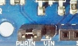
To control two motors simultaneously, save on cables, and simplify the setup, I equipped myself with an Arduino shield: 2A Motor Driver Shield. Before we proceed to connect everything, let's begin by setting up our shield. The first thing is to change the power source selection; for our project, it should be on PWRIN because we will use an external power supply for our motors.
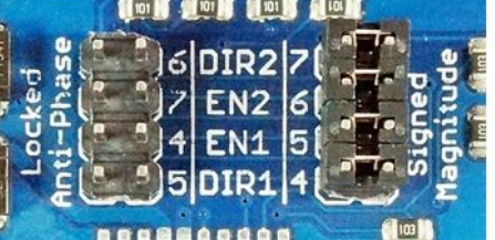
The second thing we need to take care of is motor control selection by adjusting the four mini jumpers on the shield to “Signed Magnitude”. This allows us to control the phase and rotate motors in two directions.
When everything is mounted correctly on the shield, we can move on to connecting it to the Arduino Uno or its substitute. The next phase is to connect the radio transmitter via an adapter to the board. In the adapter, you have a total of 8 pins, and we will use only 7 of them:
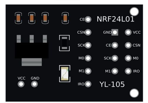
| Adapter | Arduino Uno | Description |
|---|---|---|
| VCC | [5V] | Power Supply pin 5V |
| GND | [GND] | Ground |
| CE | [D9 pin] | Chip Enable pin |
| CSN | [~D10 pin] | SPI Chip Select pin |
| SCK | [D13 pin] | SPI Clock pin |
| MO | [~D11 pin] | Slave Data Input pin MOSI |
| MI | [D12 pin] | Slave Data Output pin MISO |
| And IRQ | Active Low Interrupt pin, which we won't use! | |
I have attached the complete tank circuit below, inclusive of the two motors.
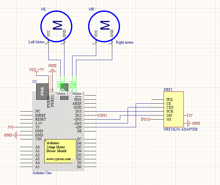
It's not crucial how you connect the motors (left and right side); later, you can simply shift the cable from A to B or from B to A (change the phase) to alter the rotating direction.
To connect an external power source, use the PWRIN input on the shield. The optimal choice would be a rechargeable battery pack: 7.4V, >1800mAh, connected via suitable connectors, and maybe even equipped with a switch. This switch will easily allow you to control the power source. Additionally, you can use this power source to supply power to the Arduino by soldering the Barrel Plug to the switch I/O. The Arduino can handle and work with a 7.4V voltage(recommended range is 7 to 12 volts), providing a single power source for both the motors and the Arduino.
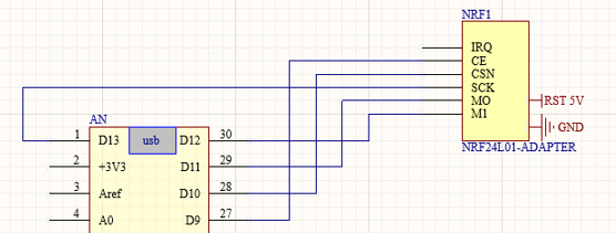
| Adapter | Arduino Nano | Description |
| VCC | [5V] | Power Supply pin 5V |
| GND | [GND] | Ground |
| CE | [D9 pin] | Chip Enable pin |
| CSN | [D10 pin] | SPI Chip Select pin |
| SCK | [D13 pin] | SPI Clock pin |
| MO | [D11 pin] | Slave Data Input pin MOSI |
| MI | [D12 pin] | Slave Data Output pin MISO |
Another part that we have to connect to control our tank is the previously mentioned joystick. This module produces an output of around 2.5V from X and Y when it is in the resting position. Moving the joystick will cause the output to vary from 0V to 5V, depending on its direction. When you connect this module to a microcontroller, you can expect to read a value of around 512 in its resting position, and when you move it to the end, the value should increase to 1023.
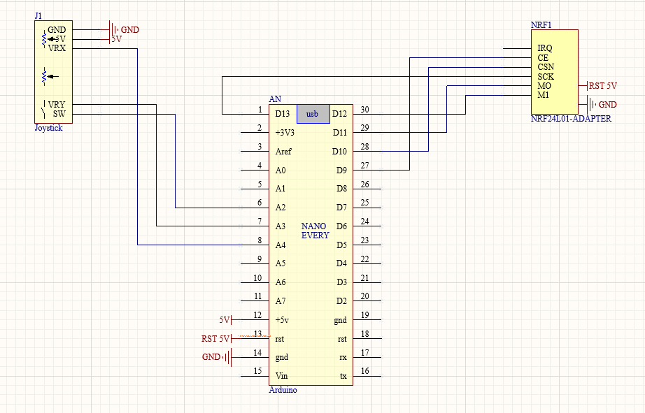
| Joystick | Arduino Nano | Description |
| GND | [GND] | Ground |
| +5V | [5V] | 5V DC |
| VRx | [A4 an. pin] | Voltage proportional to x position |
| VRy | [A3 an. pin] | Voltage proportional to y position |
| SW | [A2 an. pin] | Switch pushbutton |
For the power source, you can simply use a power bank and a USB cable.
Construction
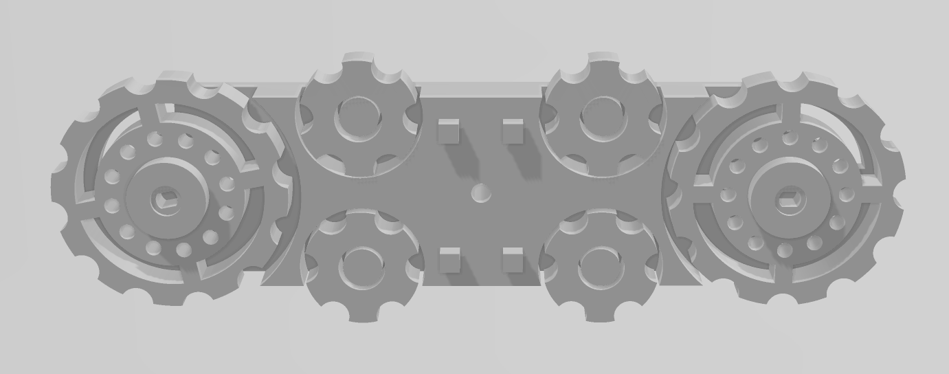
After connecting all the tracks (32 for both sides), you can place them on the cogs. Don't hesitate to use a bit more force; it shouldn't break. Additionally, I recommend securing the 'Side' with the 'Side bumper' using rope or paper clips in the middle hole designed for this purpose.
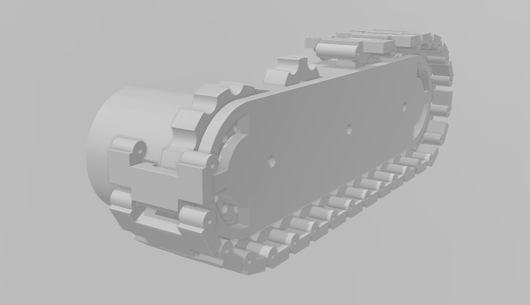
The final step is to guide the cables from the motors between the holes in the body and press-fit everything together. If the clips don't hold it securely enough, you can either try reprinting it or simply use some tape on the bottom – nobody will notice.
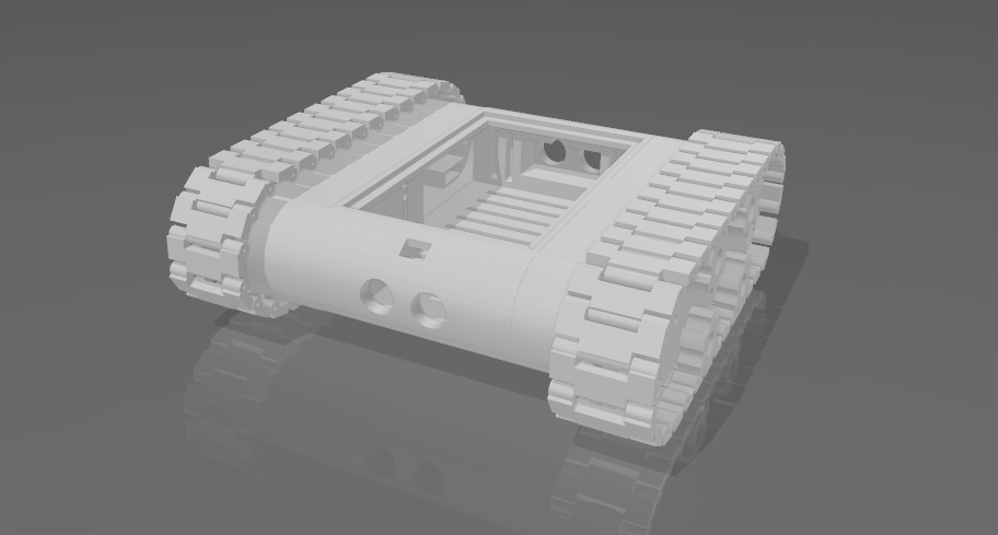
Now that you've completed these steps, you're halfway through(https://www.thingiverse.com/thing:5975570).
Software description
Conclusions
Comments
SEPPI
- 03 December, 2024
Amazing project
Leave a comment